










Find the Ultimate Low-Speed BLDC Motor for Your Project
 Sep 23, 2026|
 View:75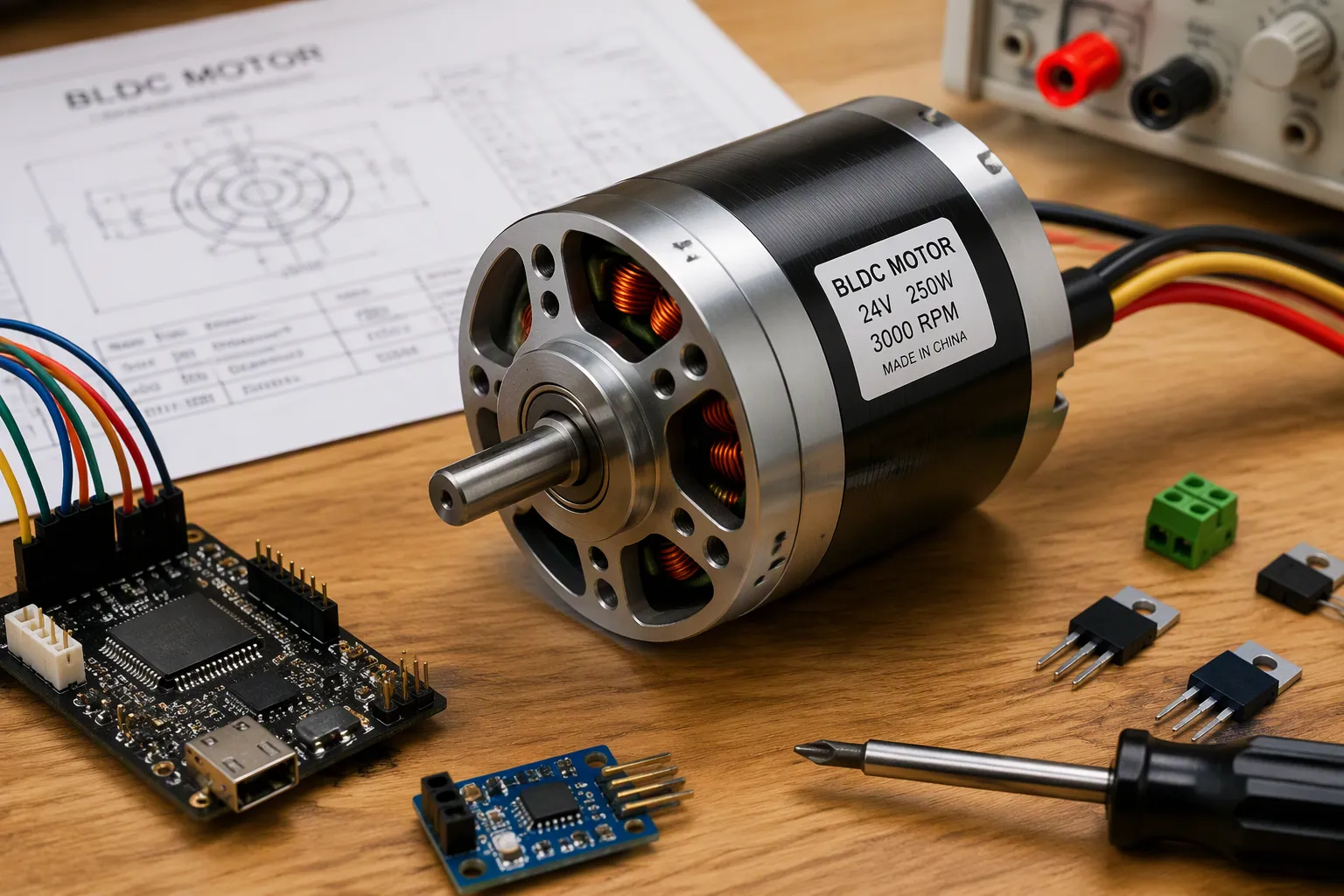
When engineers select a low-speed bldc motor, torque at low RPM matters far more than top RPM or wattage. A brushless dc motor with insufficient torque cannot turn the load at the commanded speed. The motor stalls, the windings overheat, and the controller may trip on overcurrent faults.
This guide walks through the selection process. Readers begin with load requirements, move through specifications and controller compatibility, then evaluate size, mounting, and motor type. Each stage builds toward a confident final decision.
A practical checklist follows before any purchase. Proper sizing for every motion control application starts with the load, not the datasheet. A brushless motor matched to real demand outperforms an oversized one.
Key Takeaways
Start with your load: calculate the torque and speed your project needs before looking at motors.
Match your motor and controller: check voltage, current, and interface compatibility to avoid failures.
Choose the right motor type: direct drive for simplicity and quietness, geared for more torque.
Test your motor on a bench: measure torque, heat, and vibration to catch problems early.
Use a checklist: verify specs, size, and cost to ensure a reliable and efficient motor selection.
Motor Sizing: Load First
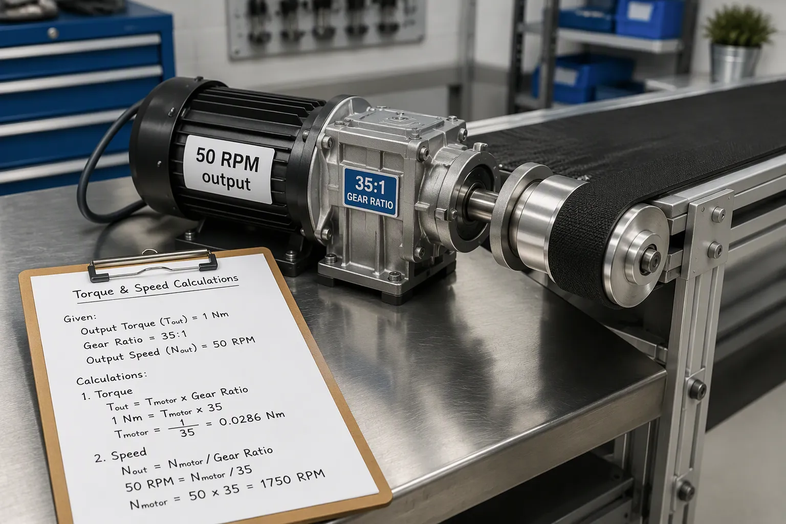
The motor sizing process begins with the application load. Selecting a low-speed bldc motor requires careful attention. Every motion control project needs a clear definition of the torque demanded by the load, the speed at which it must move, and the duty cycle that governs thermal stress. Choosing a brushless motor without quantifying these values leads to stalling, overheating, and controller faults. The motor sizing process therefore starts at the mechanical load, not the motor datasheet.
Calculate Torque and Speed
The first step in motor sizing is determining the required rotational force at the drive shaft. For a low-speed conveyor, this calculation follows a straightforward procedure.
Determine the required rotational force at the conveyor drive shaft. Calculate this value from the belt pull and the pulley radius.
Divide the drive-shaft rotational force by the gearbox ratio and efficiency to obtain the required motor output.
Convert the motor output and motor revolutions per minute into the required motor power in kilowatts.
Apply a service factor of 1.5 to 2.0 to account for shock loads and start-up demands.
A worked example clarifies the process. Suppose a conveyor must move at 50 RPM. A standard 1750 RPM motor requires a gearbox reduction of roughly 35:1. If the load produces a force of 20 N on a pulley with a radius of 5 cm (0.05 m), the required rotational force equals 20 N multiplied by 0.05 m, or 1 Nm. This value is the minimum at the output shaft. The motor must produce more than this figure after accounting for gearbox efficiency and the service factor.
The same conveyor belt under 2,000 RPM presents a different challenge. Higher revolutions per minute reduces required rotational force proportionally but places greater demands on bearing selection and rotor balance. The motor's torque must still exceed the load demands across the full operating range.
An EV-style application at 2 to 3 kW and 48V nominal operates in a different regime. High power at low voltage demands high current. The motor winding resistance must be low to minimize I²R losses. The controller must handle the current without overheating.
A lightweight low-speed target adds further complexity. A motor rated at 150W to 250W operating at 300 to 500 RPM and weighing under 2 kg is difficult to find. Such a combination requires high pole count and careful magnetic design to generate adequate torque output at low speed without adding mass. Standard catalog motors rarely meet this combination of power, rotational speed, and weight simultaneously. Using a motor sizing calculator can simplify these calculations by accepting load mass, pulley radius, gearbox ratio, and desired speed as inputs.
Define Duty Cycle and Environment
Duty cycle determines how the motor handles thermal stress over time. A continuous duty application, such as a 24/7 conveyor in a warehouse, demands that the motor maintain its rated output indefinitely without overheating. Tests confirm that motors built for continuous operation sustain their rated rotational force under cyclical warehouse loads. This rating confirms a 100 percent continuous duty cycle rather than an intermittent one.
An intermittent duty application allows the motor to cool between active periods. Higher peak loads become possible because the motor does not run long enough to reach thermal equilibrium. Torque capacity during the active period can exceed the continuous rating by a safe margin determined by the duty cycle ratio.
Environmental factors also affect the motor sizing decision. Ambient temperature, humidity, dust, and vibration all influence winding life and bearing reliability. A motor operating in a clean, climate-controlled facility faces less thermal stress than one exposed to outdoor conditions or washdown environments. Enclosure selection must match the environment. An IP54 rating offers protection against dust and splash, while IP65 or higher suits wet or outdoor locations.
The motor's physical integration with the gearbox and controller must also be considered. The gearbox reduces the motor's high rotational speed to match the target output speed. A standard 1750 RPM motor driving a 50 RPM shaft needs a ratio of about 35:1. The closest standard ratio is selected, and fine-tuning is achieved through variable frequency control. Gearbox type matters: helical designs offer 95 to 98 percent efficiency, worm drives range from 50 to 90 percent with self-locking capability, and planetary gearboxes provide high torque density in a compact package.
A common mistake occurs when engineers calculate steady-state load only. Startup and jam conditions can demand two to three times the steady-state torque. The motor and gearbox must both handle these peak events without damage. Another mistake involves using unrealistic friction coefficients. A dirty slider bed has higher friction than a clean, new one. Field-realistic values should always be used in the motor sizing calculation.
Power and Torque Requirements
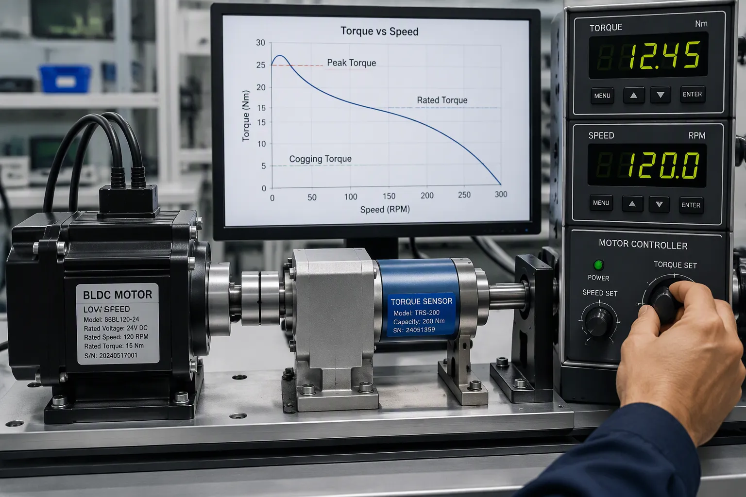
After the load and duty cycle are defined, the analysis turns to power and torque requirements. A brushless motor must supply the required torque at every point within the operating speed range. Three quantities define the rotational capability: rated torque, peak torque, and cogging torque. Each influences motor performance and system reliability. The relationship between torque and speed is fundamental to motor selection. Low-speed applications demand high torque.
Rated Torque, Cogging Torque, Pole Count
Rated torque is the continuous rotational force the motor can deliver without exceeding its thermal limit. Peak torque is the maximum force available for short periods, such as during startup or momentary overload. Cogging torque (CGT) is the energy variation from the interaction between permanent magnets and stator slots. CGT reduces the average pull and introduces torque ripple. At speeds below 100 RPM, this ripple can cause instability. Advanced controllers use anti-cogging features that map and compensate cogging harmonics. Empirical FFT analysis confirms that those harmonics appear at multiples of the slot count and pole pair number. This compensation enables smooth low-RPM, high-torque operation.
A BLDC motor’s maximum speed typically falls between 5,000 RPM and over 15,000 RPM. Because gearboxes can only tolerate a limited input speed, matching the gearbox and brushless motor correctly is essential for reliable performance.
A gearbox alters both speed and torque, so the motor should not be chosen based only on final output torque.
Simplified output torque relationship: T_output = T_motor × G × η_g
T_output = gearbox output torque
T_motor = motor torque
G = gear ratio
η_g = gearbox efficiency
Example: motor torque = 0.20 N·m, gear ratio = 10:1, gearbox efficiency = 85% → T_output = 0.20 × 10 × 0.85 = 1.7 N·m
The application must still be checked against the gearbox’s rated torque, speed, and service-life limits.
Therefore, the motor and gearbox should be evaluated as one drive system, especially for reduced-speed, higher-torque applications.
Higher pole count improves low-speed torque because more magnet poles interact with the stator windings per revolution. However, it also increases cogging and limits maximum speed. Selecting the right pole count balances smoothness, force density, and speed range.
The speed-torque operating point must fall within the motor’s continuous and peak power ratings. A motor performance curve shows the safe region. Operating outside that curve leads to overheating or stalling. The motor sizing process now includes the torque by speed profile and the limits imposed by gearbox input speed.
Winding Resistance and Kv Rating
The Kv rating expresses motor speed per volt in RPM/V. The torque constant Kt is the inverse of Kv after unit conversion. In SI units, Kt = 1/Kv. For Kv given in RPM/V, Kt = 9.549 / Kv (in Nm/A). A 1000 Kv motor has Kt = 9.549 / 1000 = 0.00955 Nm/A (about 9.55 mNm/A). Each ampere of current produces roughly 9.55 mNm of torque. Because torque is directly proportional to current (T = Kt × I), a lower Kv motor yields higher torque per amp.
Kv Category | Typical Kv Range | Torque Behavior | Speed Behavior | Winding Characteristic | Suitable Applications |
|---|---|---|---|---|---|
Low Kv | 500–1500 KV | Higher torque per ampere | Lower rotational speed | Many thin wire windings producing stronger magnetic fields per ampere | Heavy-duty, low-speed, high-torque tasks (e.g., direct-drive) |
High Kv | 3000–6000 KV | Lower torque | Greater speed | Fewer but thicker wire windings carrying more current at lower voltage | High-speed applications with light loads |
The key insight is that Kv is inversely related to the number of wire windings in the stator. A low Kv motor provides superior torque per ampere and better efficiency for low-speed, high-torque applications. For example, a direct-drive conveyor benefits from a low Kv motor because the required torque is high and the speed is low. Conversely, a high Kv motor would need gearing to multiply torque but could achieve higher speeds. Winding resistance (phase resistance) affects copper loss. Lower resistance reduces I²R heating, which is critical when high current flows at low voltage. In an EV-style application at 48V, winding resistance must be minimized to keep efficiency high. The controller must also be rated for the peak current the motor draws.
The torque capacity at low speeds depends heavily on the Kv and winding resistance combination. Matching these parameters to the load ensures reliable operation. The continuous and peak power ratings define the allowable thermal envelope. The motor performance curve should always be verified against the actual speed-torque operating point.
Controller Compatibility
Control interfaces rank alongside specifications, environment, and cost as key selection factors. A brushless motor must communicate with its controller through a compatible interface. Common options for 48V systems include:
PWM input, the most common speed control method for microcontroller systems
Analog voltage input, which varies speed through voltage changes and suits simple systems
Communication-based inputs such as UART, CAN bus, RS485, I²C, and SPI for industrial automation, EVs, and robotics
RS232 and RS485 for legacy industrial equipment
To ensure ultra-smooth commutation at low speeds, Baolong offers Brushless Motors with Integrated Drivers. By embedding the FOC (Field Oriented Control) driver directly into the motor housing, we eliminate EMI issues caused by long phase cables and ensure precise torque control even at speeds below 10 RPM.
Sensored vs. Sensorless
The choice between sensored vs sensorless operation depends on the application's speed range and precision needs. Sensored motors use Hall sensors or encoders to report rotor position directly. Sensorless controllers infer rotor position from back-EMF detection. The controller must support sensorless back-EMF detection to operate without Hall sensors or encoders.
Sensorless operation works best at medium to high speeds. The motor's operating speed range must align with this limitation. At low speeds, back-EMF signals weaken, and position estimation becomes unreliable. The motor and bearings must remain in good condition to maintain accurate back-EMF readings. The controller should also support sensorless control mode alongside options like FOC, sinusoidal, or trapezoidal commutation to match the motor's performance needs.
Voltage and Current Limits
Voltage and current ratings must match between motor and controller. Low-voltage options (24–48VDC) suit battery-powered and compact systems. High-voltage options (220–380VAC) serve industrial installations. A 48V motor requires a controller rated for 48V nominal input. Exceeding the controller's voltage limit damages internal components.
Current limits protect both devices. The controller must supply the motor's peak current demand without overheating. Winding resistance determines how much current the motor draws at a given voltage. A mismatch causes nuisance trips or insufficient torque. Always verify that the controller's continuous and peak current ratings exceed the motor's requirements.
Size and Mounting
Physical dimensions determine whether a motor fits the available space. Weight affects the structural support required. Shaft geometry governs coupling to the load. These factors often eliminate otherwise suitable candidates. Engineers should measure the mounting envelope before reviewing torque curves.
Dimensions, Weight, and Shaft
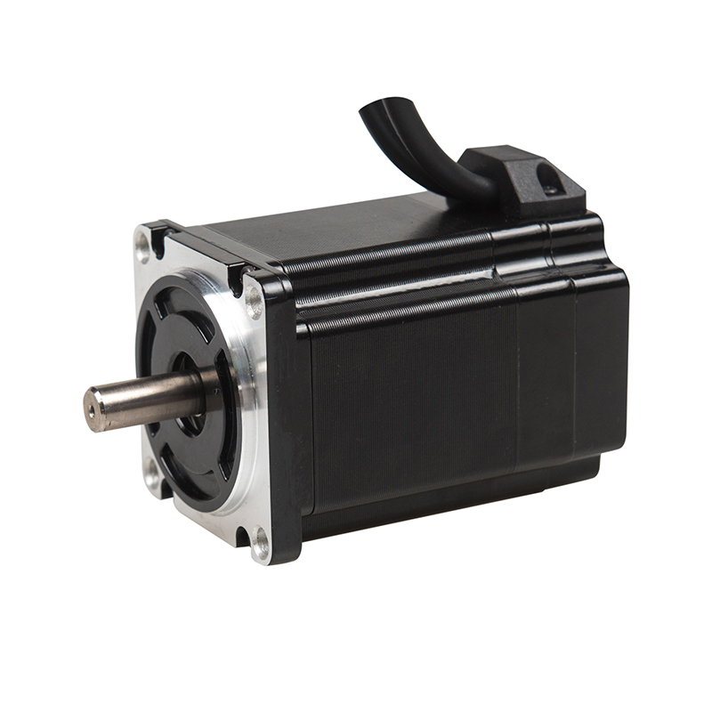
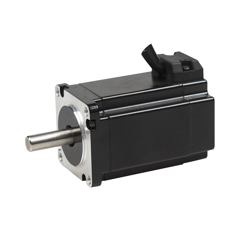
A NEMA 23 frame illustrates common mounting dimensions for low-speed BLDC motors. The mounting face measures 57mm by 57mm (2.25 in by 2.25 in). Four mounting holes accept M5 or #10-24 threading. The diagonal bolt spacing is 47.14mm. The shaft diameter is 6.35mm (0.25 in). Motor length ranges from 39mm to 114mm depending on stack length and winding configuration.
NEMA 23 BLDC motors have the same mounting dimensions as NEMA 23 stepper motors.
This compatibility simplifies replacement and prototyping. A design that already accommodates a NEMA 23 stepper motor can accept a NEMA 23 BLDC motor without new brackets or shaft adapters. The motor type and size therefore influence mechanical integration as much as electrical performance.
Mounting configurations include two common options:
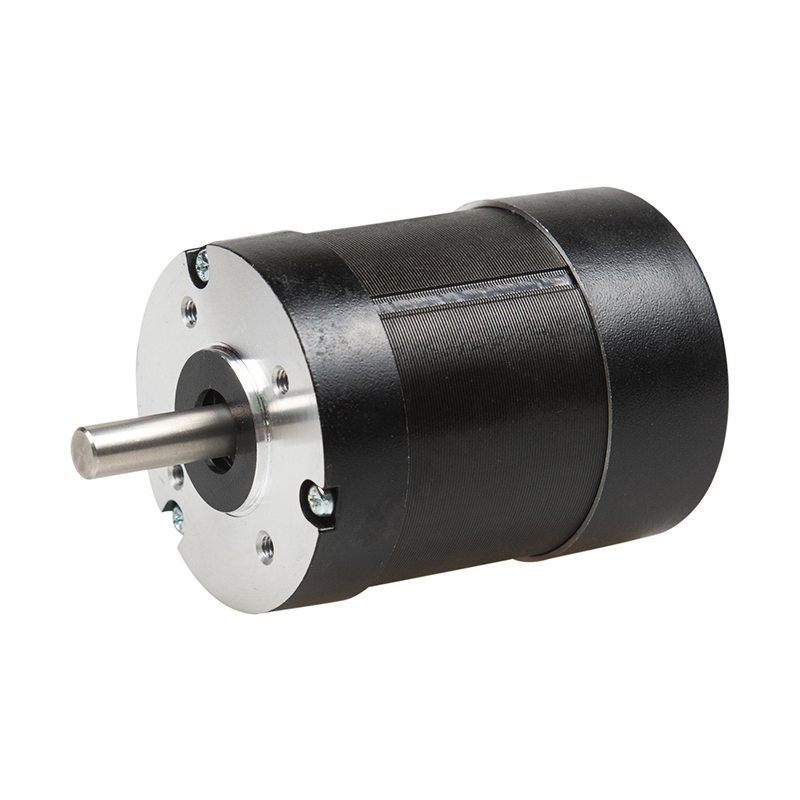
Round flange mounting design optional
Square flange mounting design optional
The square flange provides a larger contact area for heat dissipation. The round flange suits applications with limited clearance around the motor body. Weight varies with motor length and housing material. A longer stack adds mass but also increases torque capacity. The mounting structure must support the motor weight plus any axial and radial loads from the coupling.
Connectors and Cables
Connector selection affects installation time and long-term reliability. Hall sensor cables, phase wires, and encoder lines each require appropriate connectors. Industrial environments often demand IP-rated connectors for dust and moisture protection. A mismatched connector forces field modifications that void warranties.
To meet harsh industrial environments, Baolong offers extensive customization options. We provide IP65-rated enclosures for wet or dusty conditions, aviation plugs for secure and rapid field wiring, and the option to mount electromagnetic brakes directly to the motor shaft—ensuring loads are held safely at zero speed during power loss.
Cable routing must account for bend radius and strain relief. Sharp bends damage conductor insulation over time. Flexible cables resist fatigue in moving applications. Shielded cables reduce electromagnetic interference with sensor signals. The cable length between motor and controller also affects voltage drop and signal integrity. Longer runs require larger conductor gauges to maintain performance.
Low-Speed BLDC Motor: Direct Drive vs. Geared
After torque targets are set, the next decision concerns how the motor produces that effort. Direct coupling connects the rotor to the load. A gearbox lets the motor spin faster and reduce RPM afterward. The correct choice depends on the speed range and the load profile.
When Direct Drive Wins
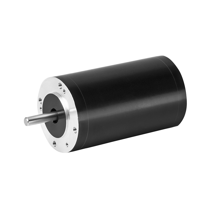
Direct drive suits applications that run at constant RPM and need immediate load response. Removing the gearbox eliminates backlash, gear wear, and lubrication schedules. Baolong’s Outer Rotor Brushless Motors are specifically engineered for these scenarios. Unlike standard inner-rotor motors, our outer rotor design features a high pole count and large diameter, generating massive torque at low RPMs without the maintenance of a gearbox. Turntables, robotic joints, and camera platforms benefit from this quiet, precise positioning.
A lightweight 150W–250W motor at 300–500 RPM under 2 kg shows why direct drive works. The motor holds its rated effort at working RPM; drive electronics stay simple, and dynamic response improves. For low-speed, high-torque jobs that must run uninterrupted, direct drive removes an entire class of failure points. Understanding pmsm vs bldc vs coreless construction still matters for cogging and ripple in low-speed operations, but the load remains the deciding factor.
Direct drive also wins when noise matters. Gearboxes add whine and vibration. Direct coupling keeps the drivetrain quiet and reduces maintenance.
When a Gearbox Helps
A gearbox multiplies torque: the output effort equals motor effort multiplied by gear ratio and gearbox efficiency. This relation lets a smaller, lower-cost brushless motor drive a heavy load without excessive current. In a 48V mobility application, a 2–3 kW motor running at high RPM with a reduction stage produces wheel effort while keeping motor current moderate.
Gearing also helps when the low-speed BLDC motor must operate inside a specific speed band. A motor designed for 5,000 RPM or more does not naturally run well at 300 RPM with full effort. A gearbox keeps the motor near its efficient range while the output runs at the needed RPM. Yet the gearbox adds backlash, weight, cost, and heat. Its input RPM limit must be checked before pairing. If the load demands extreme effort at low RPM, a larger direct-drive motor may prove simpler and more reliable.
Testing and Validation
Bench testing confirms whether a motor meets its calculated requirements before installation. This step catches mismatches between specifications and real-world performance.
Bench Testing Torque and Heat
A dynamometer measures output torque across the operating speed range. The test should replicate the actual duty cycle, including startup and peak load events. Record winding temperature throughout the run. A motor that exceeds its thermal limit during bench testing will fail in the field.
Thermal imaging identifies hot spots in the windings and bearings. Temperature rise under load reveals whether the cooling design suits the application. For continuous duty applications, the motor must reach thermal equilibrium without exceeding its insulation class rating. Intermittent duty tests show how quickly the motor recovers between cycles.
Measure torque ripple at the target operating speed. Excessive ripple indicates cogging or commutation issues that affect smoothness. A brushless motor with poor low-speed commutation shows unstable output even when average torque meets the target.
Red Flags During Trials
Several warning signs indicate the motor or controller selection needs revision. Vibration, noise, and speed fluctuation often point to commutation problems.
Sensorless control cannot detect rotor position at standstill or very low speeds because back-EMF is only present when the motor is moving. This makes low-speed operation poor and startup challenging, which can serve as an early indication that commutation may become improper under such conditions.
Watch for these specific indicators during bench trials:
Inaccurate rotor position estimation in sensorless BLDC systems can cause unstable operation and noticeable vibration.
Improper commutation timing can contribute to noise and vibration issues.
Poor feedback control can lead to speed fluctuation, oscillation, or slow response, which may indicate commutation is not being applied correctly at low speed.
Any of these signs warrants investigation before final purchase. A motor that performs well on paper but fails during trials will not succeed in production.
Brushless Motor Selection Checklist
Specs-to-Project Match
A brushless motor selection checklist prevents costly mismatches. Start with the load profile. Confirm the required torque at the target speed. Verify the duty cycle against the motor's thermal rating. Check the controller interface and voltage. Measure the mounting envelope. These steps connect the application to the datasheet.
When sourcing low-speed bldc motors, partnering with an experienced manufacturer is critical to avoid thermal and commutation failures. Baolong Motor brings over 20 years of specialized manufacturing experience to these exact challenges. Operating a 17,000 m² state-of-the-art facility, Baolong excels in customizing low-speed drive solutions. Whether you need a high-torque outer rotor motor for direct-drive robotics, or a gearbox-integrated BLDC for heavy logistics AGVs, Baolong provides tailored solutions ranging from 5W to 3kW (22mm-130mm base sizes) across 24-48VDC and 220-380VAC platforms.
The table below shows representative standard BLDC motor models from Baolong's catalog. Note: While these standard core motors operate at higher base speeds (e.g., 5000 RPM), they are routinely paired with Baolong's high-efficiency planetary gearboxes (ratios from 10:1 to 100:1) to achieve target low-speed RPMs (e.g., 50-300 RPM) while multiplying output torque exponentially. Alternatively, explore our Outer Rotor Series for direct-drive low-speed solutions.
Motor Model | 46ELTH244050 | 46ELTH246050 | 46ELTH248050 |
|---|---|---|---|
Rated Voltage (VDC) | 24 | 24 | 24 |
Rated Speed (Rpm) | 5000 | 5000 | 5000 |
Rated Torque (N.m) | 0.08 | 0.12 | 0.16 |
Rated Power (W) | 40 | 60 | 80 |
Rated Current (A) | 2.5 | 3.8 | 5.1 |
Peak Current (A) | 7.5 | 11.4 | 15.2 |
Peak Torque (N.M) | 0.24 | 0.36 | 0.48 |
Need a Custom Low-Speed BLDC Solution?
Standard catalog motors rarely fit unique low-speed, high-torque applications perfectly. At Baolong, we offer multiple shaft options, integrated brakes, and custom winding configurations to match your exact load profile. Contact our engineering team today for a free torque-speed curve analysis and 3D CAD models.
Cost vs. Performance
Budget constraints often push buyers toward lower-cost units. A cheaper brushless motor may lack the torque margin for peak loads. It may run hotter under continuous duty. Replacement and downtime costs can exceed the initial savings. Balance purchase price against efficiency, thermal performance, and expected service life.
Baolong claims about 15% shorter motor length for the same output. The company also reports roughly 20% lower temperature rise under identical conditions. These benefits reduce mounting space and thermal stress. Baolong provides free support and a warranty with free replacement for quality issues. Buyers should treat these claims as a starting point for their own sizing and testing.
The decision path begins with load requirements, then moves through specifications, controller compatibility, size, motor type, and testing. Each step eliminates mismatched options. The best motor matches the project's actual torque, speed, and budget, not the most powerful rating. Always apply the brushless motor selection checklist and validate with a bench test before final purchase. Bench testing catches thermal and commutation issues that datasheets miss. Skipping these steps often leads to stalling or overheating in the field. Use the checklist to confirm each parameter matches the project. This process ensures reliable, long-term performance. Without a proper bench test, hidden issues can cause field failures. A thorough evaluation saves time and money by preventing costly redesigns. Start sizing your low-speed BLDC motor today.
FAQ
Does a higher wattage rating guarantee better low-speed performance?
No. Wattage describes power, not the rotational force available at low RPM. A motor with modest wattage and a low Kv winding can out-pull a higher-wattage unit at 300 RPM. Always compare rated torque at the target speed, not the nameplate power figure.
Why do sensorless controllers struggle below a few hundred RPM?
Back-EMF weakens as speed drops, so the controller loses reliable rotor position data. Startup and very low-speed operation become unstable. A sensored motor with Hall sensors or an encoder solves this problem. Choose sensorless control only when the operating range stays at medium to high speed.
When should a gearbox replace a direct-drive setup?
A gearbox multiplies torque and keeps the motor near its efficient speed band. Direct drive wins when backlash, noise, and maintenance must stay minimal. If the load needs extreme torque at very low RPM, a larger direct-drive motor often proves simpler and more reliable than adding a reduction stage.
Can a 48V motor run on a 24V controller?
No. Voltage ratings must match between motor and controller. A 48V motor needs a controller rated for 48V nominal input. Low-voltage systems span 24–48VDC, while industrial options run 220–380VAC. Exceeding the controller's voltage limit damages internal components and voids warranties.
How do I choose the right gearbox ratio for a low-speed BLDC motor?
The gear ratio depends on your target output RPM and the motor's base speed. For example, pairing a 3000 RPM Baolong BLDC motor with a 30:1 planetary gearbox yields an output of 100 RPM while multiplying the torque by approximately 25x (accounting for efficiency losses). Baolong's engineering team can help you calculate the exact gearbox ratio and service factor required for your specific shock loads.
Is a lightweight low-speed motor under 2 kg realistic?
It is difficult but possible. A 150W–250W motor at 300–500 RPM under 2 kg demands high pole count and careful magnetic design. Standard catalog units rarely meet all three targets at once. Custom manufacturing, such as frameless BLDC configurations, becomes the practical route.
Recent News
1.DC Brush Motor and DC Brushless Motor difference
2022-07-132.Gearbox Brushless Motor and the difference between the Brush Motor
2022-10-103.Top 10 Brushless Motor Manufacturer for 2026: Expert Guide to Choosing the Right Supplier
2024-07-124.Maintenance and Troubleshooting Tips for 48V DC Brushless Motors
2024-12-165.A Comprehensive Analysis Tell You Why Are Brushless Motors Better!
2025-06-26