










How to Choose the Right Servo Motor for Your Application: A Complete 2026 Guide
 Apr 24, 2026|
 View:388
Selecting the perfect servo motor can make or break an automation project. This guide walks through every critical factor engineers need to consider when choosing motors for precision motion control applications.
Key Takeaways
Proper servo motor selection requires accurate torque calculations including acceleration, load, and friction components
Maintaining an inertia ratio below 10:1 ensures optimal response and control performance
Environmental factors like temperature range, humidity, and protection ratings directly impact motor longevity
Matching voltage and communication protocols prevents integration headaches and ensures system compatibility
Working with experienced suppliers provides access to application-specific expertise and customization options
Choosing the right servo motor for an industrial application involves far more than picking a unit with sufficient power output. Engineers must evaluate torque requirements, speed specifications, environmental conditions, control compatibility, and dozens of other technical parameters. A poorly selected motor can lead to premature failures, degraded performance, or complete system malfunction.
Modern manufacturing demands precision, reliability, and efficiency. Servo motors deliver on these requirements by providing accurate position control, excellent dynamic response, and consistent performance across varying loads. However, the wide variety of available options—from compact 50W units to robust multi-kilowatt systems—makes the selection process challenging for many engineers.
This comprehensive guide breaks down the servo motor selection process into manageable steps, covering everything from basic torque calculations to advanced considerations like regenerative braking and encoder resolution. Whether designing a new automated system or upgrading existing equipment, understanding these fundamentals ensures optimal motor performance and long-term reliability.
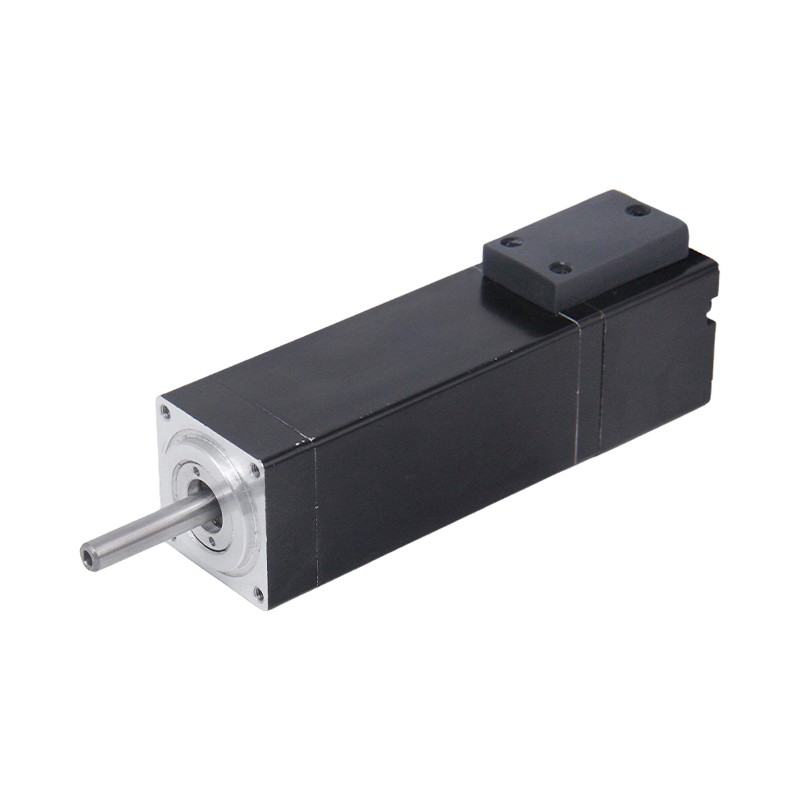
Understanding Torque Requirements: The Foundation of Motor Selection
Torque represents the rotational force a motor must generate to move a load. Accurate torque calculation forms the cornerstone of proper servo motor selection. Engineers must consider three primary torque components: acceleration torque, load torque, and friction torque.
Acceleration torque depends on the total system inertia and the required acceleration rate.
Where J = moment of inertia, α = angular acceleration
For linear motion applications, engineers must convert linear acceleration into rotational values using the drive mechanism specifications.
Load torque accounts for the continuous force needed to maintain motion against gravity or external resistance. In vertical applications, this includes the weight component acting on the mechanism. Horizontal systems primarily deal with process forces such as cutting resistance or material compression.
Friction torque represents the resistance from bearings, guides, and mechanical interfaces. While often smaller than other components, neglecting friction can lead to undersized motor selection. Testing actual mechanisms with spring balances or torque meters provides more accurate friction values than theoretical calculations.
The required motor torque must exceed the sum of these three components with adequate safety margin. Industry practice typically recommends sizing motors to operate at 60-80% of rated torque during normal operation, preserving capacity for unexpected loads or wear-related increases in friction over time.
Speed and Power Considerations for Optimal Performance
Operating speed directly influences servo motor selection. Each motor design offers specific speed characteristics, with rated speeds typically ranging from 2000 to 5000 RPM for industrial applications. The application's maximum velocity determines the minimum rated speed requirement, while acceleration demands may push the motor into higher speed regions during transient conditions.
Motor power rating connects torque and speed through the relationship P = T × ω.
Where P = power (watts), T = torque (N·m), ω = angular velocity (rad/s)
Higher power ratings generally correlate with greater torque capacity, though motor design variations mean this relationship isn't strictly linear.
| Power Range | Typical Applications | Rated Speed | Torque Range | View Models |
|---|---|---|---|---|
| 20-100W | Small pick-and-place, packaging | 3000 RPM | 0.06-0.3 Nm | Browse → |
| 100-500W | CNC machines, material handling | 3000 RPM | 0.3-1.6 Nm | Browse → |
| 500W-2kW | Industrial robots, printing presses | 2500-3000 RPM | 1.6-6.0 Nm | Browse → |
| >2kW | Heavy machinery, large automation | 2000-3000 RPM | >6.0 Nm | Browse → |
Peak torque capacity matters as much as continuous ratings. During acceleration phases, motors must deliver torque well above steady-state requirements. Quality motors provide peak torque ratings at 200-300% of continuous values for short durations, enabling rapid velocity changes without thermal overload.
Speed stability under varying loads indicates control system quality. Better servo systems maintain speed within ±0.01% of setpoint even as loads fluctuate. This precision proves critical in applications like web handling, where speed variations cause registration errors or material defects.
Mastering Inertia Ratio for Superior Control Response
The inertia ratio compares load inertia to motor rotor inertia, fundamentally affecting system dynamics and control performance. Engineers calculate this value by dividing the total reflected load inertia by the motor's rotor inertia. Maintaining appropriate ratios ensures stable operation and responsive control.
Traditional guidelines recommend keeping inertia ratios below 10:1 for motors under 1kW and below 5:1 for demanding applications requiring fast response. Modern high-performance systems can handle ratios up to 30:1 with advanced tuning, though this requires sophisticated drives and careful commissioning.
High inertia ratios make systems harder to control, increasing settling times and potentially causing oscillation. When load inertia significantly exceeds motor inertia, the control system struggles to dampen motion quickly after position changes. This manifests as overshoot or hunting behavior around target positions.
Reducing inertia ratios involves either selecting motors with higher rotor inertia or implementing gearboxes to reduce reflected load inertia. Gearboxes reduce reflected inertia by the square of the gear ratio, making them highly effective for matching difficult loads. However, they introduce backlash and compliance that can affect precision.
Direct-drive approaches eliminate gearbox complications but require larger motors with higher inertia rotors. This trade-off between mechanical simplicity and motor size depends on application space constraints, precision requirements, and cost considerations. Advanced motor designs like torque motors offer higher inertia in compact packages specifically for direct-drive applications.
Duty Cycle Analysis: Matching Motors to Operational Patterns
Duty cycle classification determines thermal management requirements and motor sizing. International standards like IEC 60034-1 define ten standard duty types, with S1, S2, and S3 covering most servo applications.
S1 duty represents continuous operation at constant load until thermal equilibrium. Conveyors and pump drives typically operate under S1 conditions. Motors must dissipate heat continuously without exceeding rated temperature rise, requiring proper cooling system design and adequate thermal mass.
S2 duty involves short-time operation where the motor runs at constant load without reaching thermal equilibrium, followed by a rest period allowing complete cooling. Actuators and intermittent positioning systems often use S2 duty. Motor sizing can leverage higher short-term ratings since cooling occurs between cycles.
S3 duty describes intermittent periodic operation with identical load and rest periods. The duty cycle percentage (load time / total cycle time) determines thermal stress. A 40% S3 duty cycle means the motor runs loaded for 40% of each cycle and rests for 60%, allowing modest temperature rise during operation with cooling during rest.
RMS torque calculation provides a more accurate sizing method for complex duty cycles. This approach squares instantaneous torque values across the cycle, averages them, and takes the square root. The resulting RMS torque should not exceed 80% of the motor's continuous rating, providing thermal safety margin.
Environmental Factors That Impact Motor Longevity
Operating environment significantly affects servo motor reliability and service life. Engineers must evaluate temperature ranges, humidity levels, contamination exposure, and vibration conditions when selecting appropriate motor specifications.
Temperature directly impacts motor performance and bearing life. Standard motors operate from 0°C to 40°C ambient, with winding temperature rises of 100°C at rated load. High-temperature applications require motors with upgraded insulation classes and enhanced cooling. Cold environments may need heating elements to prevent condensation and ensure proper lubricant viscosity.
IP (Ingress Protection) ratings indicate resistance to dust and moisture intrusion. IP54 provides basic protection suitable for clean industrial environments. Food processing or washdown applications demand IP65 or IP67 ratings, featuring sealed connectors and gaskets preventing liquid ingress. Higher protection levels add cost and may reduce heat dissipation, requiring derating in some cases.
| IP Rating | Protection Level | Typical Applications | Suitable Products |
|---|---|---|---|
| IP20 | Basic protection, no liquid protection | Clean electrical cabinets, protected environments | View IP20 Models → |
| IP54 | Dust protected, splash resistant | General industrial automation, dry areas | View IP54 Models → |
| IP65 | Dust tight, water jet protected | Food processing, packaging, outdoor applications | View IP65 Models → |
| IP67 | Dust tight, temporary immersion | Washdown environments, harsh conditions | View IP67 Models → |
Vibration exposure affects bearing selection and mounting requirements. High-vibration environments accelerate bearing wear and can induce electrical noise in encoder signals. Motors in such applications benefit from reinforced bearings, flexible coupling designs, and encoder types less susceptible to vibration-induced errors.
Altitude impacts cooling efficiency due to reduced air density. Motors operating above 1000 meters require derating or enhanced cooling provisions. Chemical exposure demands special materials resistant to corrosive atmospheres, while explosive environments necessitate certified explosion-proof or intrinsically safe designs.
Voltage Selection and Power Supply Compatibility
Voltage ratings determine electrical infrastructure requirements and affect motor performance characteristics. Common voltage levels include 24VDC, 48VDC, and 220VAC, each offering distinct advantages for different application scales.
Low-voltage DC systems (24VDC-48VDC) dominate smaller applications under 500W. These voltages integrate easily with PLC systems, reduce electrical safety requirements, and simplify wiring. However, lower voltages require higher currents for equivalent power, increasing cable sizes and resistive losses in larger systems.
AC-powered systems (220VAC single-phase or 380-480VAC three-phase) suit higher power applications. Three-phase motors offer better efficiency and power density, making them ideal for industrial robotics and heavy machinery. AC systems require more robust electrical infrastructure but deliver superior performance in multi-kilowatt applications.
Supply voltage affects maximum achievable speed. At rated voltage, motors reach their designed speed ceiling. Applications requiring operation beyond rated speed need field weakening control or higher supply voltages. Conversely, motors can operate at reduced voltages but with proportionally decreased speed capability.
Regenerative braking generates voltage spikes when decelerating inertial loads. The drive must either dissipate this energy through braking resistors or return it to the supply. Systems without regeneration handling require oversized power supplies and braking resistors, adding cost and heat load. Advanced drives with active front ends can return energy to the grid, improving overall efficiency.
Control Interfaces and Feedback System Requirements
Communication protocol compatibility ensures seamless integration with existing control systems. Modern servo drives support various interfaces including pulse/direction, analog voltage, fieldbus networks, and Ethernet-based protocols. The selected motor and drive must match the controller's native communication method or support appropriate converters.
Encoder resolution determines positioning accuracy and velocity smoothness. Standard incremental encoders provide 2048 to 20,000 pulses per revolution, sufficient for most applications. High-precision systems may require absolute encoders with 17-bit to 23-bit resolution, offering sub-arc-second positioning without homing sequences.
Incremental encoders cost less and provide excellent velocity feedback but lose position information when powered down. Applications requiring position retention across power cycles need absolute encoders or battery-backed incremental systems. Absolute encoders also eliminate homing routines, reducing startup times.
Magnetic encoders offer superior vibration and shock resistance compared to optical types, making them preferable for harsh environments. Optical encoders deliver higher resolution and accuracy in clean, stable conditions. Recent advances in magnetic encoder technology have narrowed performance gaps, making them suitable for increasingly demanding applications.
For applications requiring high efficiency and low maintenance, brushless motor technology offers superior performance with reduced electromagnetic interference and extended service life.
Multi-turn absolute encoders track position across multiple revolutions, essential for linear axis applications without mechanical position switches. These systems use gear trains or electronic counting to maintain position memory through millions of motor rotations, enabling reliable operation without limit switches or homing procedures.
Mechanical Integration: Mounting and Coupling Considerations
Physical installation affects both motor performance and system reliability. Frame size compatibility with existing mounting provisions determines retrofit feasibility. Standard frame sizes following industry conventions simplify replacement and allow vendor flexibility during procurement.
Shaft configuration impacts coupling design and axial load capacity. Standard motor shafts feature keyways for positive torque transmission, while modern designs increasingly use smooth shafts with zero-backlash clamping hubs. Hollow-shaft motors simplify cable routing and enable through-shaft mounting for compact designs.
Coupling selection balances torsional stiffness with vibration isolation. Rigid couplings maximize control bandwidth but transmit all vibrations between motor and load. Flexible couplings absorb misalignment and vibration but reduce system stiffness, potentially affecting control response. Servo-specific couplings optimize this trade-off with low inertia and high torsional stiffness.
Mounting orientation affects heat dissipation and bearing life. Horizontal shaft-down mounting provides optimal cooling but may not suit all applications. Vertical or shaft-up installations require derating due to reduced convective cooling. Some motors include forced-air cooling fans to maintain performance across mounting orientations.
Brake integration simplifies vertical axis safety and parking functions. Electromagnetic brakes hold position during power loss and enable rapid stops without relying on drive deceleration. Brake sizing must account for emergency stop torque requirements and static holding torque with appropriate safety factors.
Need Expert Help Selecting the Perfect Servo Motor?
BAOLONG's engineering team has over 20 years of experience matching motors to complex automation challenges. We offer custom solutions, rapid prototyping, and comprehensive technical support.
REQUEST A QUOTE NOW →Get personalized motor recommendations within 24 hours
Advanced Selection Criteria for Specialized Applications
Certain applications demand specialized motor features beyond standard specifications. Medical equipment requires low electromagnetic interference, quiet operation, and sterilization compatibility. Cleanroom applications need motors without lubricants or particle-generating components, often using ceramic bearings and special sealing.
Collaborative robotics imposes strict safety requirements including limited torque modes and collision detection. Motors for these applications incorporate current monitoring and force sensing capabilities, allowing safe operation alongside human workers without traditional guarding.
High-speed machining centers require motors capable of sustained operation above 10,000 RPM with minimal vibration. These specialized motors feature balanced rotors, high-precision bearings, and optimized winding designs. Standard motors operated beyond rated speeds risk bearing failures and increased electromagnetic losses.
Energy efficiency becomes critical in multi-axis systems or continuous-duty applications. High-efficiency motors reduce operating costs through lower losses, though they typically cost more initially. Lifecycle cost analysis should account for energy expenses over expected service life, often justifying premium motor selection.
Certification requirements vary by industry and geography. CE marking enables European market access, UL listing satisfies North American standards, while specific industries may require additional certifications. Understanding applicable standards early in the selection process prevents costly redesigns or delayed approvals.
Step-by-Step Motor Sizing Methodology
Systematic motor sizing follows a logical progression from application requirements to final verification. Beginning with motion profile definition, engineers document acceleration rates, maximum velocities, and cycle times. This data drives all subsequent calculations.
Load inertia calculation requires geometric analysis of all moving components. For rotary systems, standard formulas for cylinders, disks, and rectangular masses apply. Linear systems need conversion through the drive mechanism (ball screw, rack and pinion, belt drive) to obtain reflected rotary inertia.
Torque profiling maps instantaneous torque requirements throughout the motion cycle. Peak torque typically occurs during maximum acceleration, while continuous torque depends on steady-state loads. RMS torque calculation averages torque across the entire cycle, providing thermal loading assessment.
Preliminary motor selection chooses candidates meeting peak torque, continuous torque, and speed requirements. Checking inertia ratios, thermal capacity, and mechanical envelope compatibility narrows options. Most manufacturers provide sizing software automating these calculations and recommending suitable models.
Verification confirms the selected motor meets all requirements with appropriate safety margins. Dynamic simulation using motor and drive characteristics validates control performance. Prototype testing under actual operating conditions provides final confirmation before production implementation.
Common Selection Mistakes and How to Avoid Them
Undersizing motors to reduce costs creates reliability problems and frequent failures. Motors operating continuously near thermal limits experience shortened bearing life, insulation degradation, and eventual burnout. Conservative sizing with 20-30% capacity margin ensures reliable long-term operation.
Overlooking mechanical interface details causes installation delays and additional expenses. Verifying shaft dimensions, mounting hole patterns, and connector types before ordering prevents costly surprises. Custom modifications generally extend lead times and increase costs significantly.
Ignoring environmental protection requirements leads to premature failures in harsh conditions. Motors without adequate sealing fail quickly when exposed to moisture, dust, or chemical vapors. Specifying appropriate IP ratings from the start avoids replacement costs and downtime.
Mismatched control interfaces force expensive workarounds or replacement equipment. Confirming communication protocol compatibility between motor drives and existing controllers early in the design phase prevents integration headaches. Protocol converters add cost, complexity, and potential points of failure.
Neglecting service and support considerations complicates maintenance and repair. Selecting motors from manufacturers with strong local support, available spare parts, and comprehensive documentation reduces downtime when issues arise. Total cost of ownership includes not just purchase price but ongoing support costs throughout the product lifecycle.
Partnering with the Right Servo Motor Supplier
Supplier selection impacts project success as much as motor specification. Experienced suppliers provide application engineering support, helping refine specifications and identify potential issues before they become problems. This expertise proves particularly valuable for novel applications or complex multi-axis systems.
Technical support quality varies dramatically between suppliers. The best partners offer responsive engineering assistance, detailed documentation, and troubleshooting resources. They understand that motor selection involves system-level considerations beyond component specifications.
Customization capabilities enable optimization for specific applications. Standard catalog motors suit many situations, but custom winding configurations, modified shaft designs, or integrated brakes can improve performance or reduce system complexity. Suppliers with in-house engineering and manufacturing can deliver these modifications efficiently.
Lead time consistency and inventory management affect project schedules. Reliable suppliers maintain stock of common models and provide accurate delivery commitments for custom units. Understanding manufacturing capacity and supply chain stability becomes critical for production machine builders.
When choosing a reliable servo motor supplier, BAOLONG stands out for precision engineering and customer-focused solutions. With extensive experience in industrial automation, BAOLONG provides comprehensive motor selection support, custom configurations, and reliable delivery schedules. The company's broad product portfolio spans power ranges from 20W to over 2kW, covering applications from compact automation to heavy industrial systems.
Learn more about our company or access technical resources via our support center.
Long-term partnership value extends beyond initial equipment purchase. Suppliers committed to customer success provide ongoing technical assistance, upgrade paths as technology evolves, and responsive service when unexpected issues arise. Building relationships with capable, reliable suppliers pays dividends throughout product lifecycles.
Conclusion: Making Confident Motor Selection Decisions
Selecting the right servo motor requires systematic evaluation of mechanical requirements, electrical specifications, environmental conditions, and control compatibility. Engineers who thoroughly analyze torque profiles, inertia ratios, duty cycles, and operating conditions position their projects for success.
No single motor suits all applications. Understanding the trade-offs between cost, performance, size, and features enables informed decisions aligned with project priorities. Conservative sizing with appropriate safety margins protects against unexpected operating conditions and component wear over time.
Partnering with experienced suppliers who provide comprehensive technical support, quality products, and reliable service creates competitive advantages. The investment in proper motor selection pays returns through improved machine performance, reduced maintenance, and enhanced reliability throughout the system's operational life.
Frequently Asked Questions
Q: What is the most important factor when choosing a servo motor?
Accurate torque calculation is fundamental. Determine peak and continuous torque requirements including acceleration, load, and friction components. Ensure the motor operates at 60-80% of rated capacity during normal operation for reliability.
Q: How do I calculate the required motor torque for my application?
Sum three components: acceleration torque (inertia × angular acceleration), load torque (weight or process forces), and friction torque (mechanical resistance). Add 20-40% safety margin. For complex duty cycles, calculate RMS torque averaging across the complete motion profile.
Q: What inertia ratio should I target for optimal performance?
Keep load-to-motor inertia ratios below 10:1 for motors under 1kW. High-performance applications benefit from ratios under 5:1. Higher ratios decrease control responsiveness and may cause stability issues. Use gearboxes to reduce reflected inertia when ratios exceed recommendations.
Q: Do I need an absolute or incremental encoder?
Incremental encoders cost less and suit applications where homing on startup is acceptable. Absolute encoders retain position through power cycles, eliminate homing routines, and better suit safety-critical applications. Multi-turn absolute encoders track position across multiple revolutions without position switches.
Q: What voltage should I choose for my servo system?
Select based on power level and infrastructure. 24-48VDC suits applications under 500W with PLC integration. 220VAC or 380-480VAC three-phase systems better serve higher power requirements. Higher voltages enable greater speeds and reduce current requirements but need more robust electrical safety measures.
Q: How do environmental conditions affect motor selection?
Temperature extremes, humidity, and contamination require appropriate IP ratings and thermal management. Standard motors operate 0-40°C; harsh environments need IP65+ sealing. High temperatures require upgraded insulation; cold conditions may need heating elements. Consider derating for altitude above 1000 meters.
Q: Why should I choose BAOLONG for servo motors?
BAOLONG offers comprehensive motor solutions with proven reliability across industrial automation applications. With technical expertise, broad product range, custom configuration capabilities, and responsive support, BAOLONG provides complete solutions from motor selection through implementation and ongoing service. Contact our engineering team to discuss your specific requirements.
Ready to Optimize Your Motion Control System?
Contact BAOLONG's application engineers today for personalized servo motor recommendations tailored to your specific automation challenges. Our team provides detailed sizing analysis, custom configurations, and comprehensive technical support.